
Minnowbrook 2017 “Moisture In Microelectronics”
June 6, 2017CMSE 2018 Call for Presentations
October 3, 2017
A Critical Review of MIL-STD-883 Wirebond Visual Inspection Criteria
An important consideration in wirebonding is visual inspection of the deformed wire after wirebond formation. The amount of wire squash-out, placement of the bond on the pad relative to nearby circuitry, looping profiles and heel integrity are all very important aspects of wirebond interconnect inspection. Poor workmanship can lead to noncompliant bonds per visual inspection criteria and can directly impact the reliability of the finished product. Bond pad inspection prior to bonding is also a critical aspect that is often overlooked. Historically, MIL-STD-883 has served as a baseline set of visual specs related to wirebond, and package assembly in general. Many company quality documents reference MIL-STD-883 TM 2017 and TM 2010 and/or cut and paste the bond inspection criteria into internal documents.
Ball Bonds
The ball “squash” factor is an important visual indicator as to how well the bond was made. The ball bond is made when the capillary captures the FAB (free air ball) and using pressure and ultrasonic energy deforms the ball to make the bond. Mil specs require the deformed ball to be 2X to 5X the wire diameter (Fig 1). 2X is considered a good lower limit. Although many reliable automated processes form nail head bonds using .8 mil wire and the ball squash is less than 2X. A small deformed ball relative to the wire diameter reduces the bonded area and will decrease strength. The upper end of this squash factor limit of 5X is very lenient. It’s difficult to squash a ball more than 5X and even a 4X squash factor indicates overbonding and possible damage to the IC.
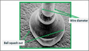
Fig. 1: Mil Spec Ball squash criteria is 2X to 5X the wire diameter
Ball squash that is less than 3.5 X is typical of a high yielding ball bonding process
The second half of the ball bond is referred to in the mil specs as the crescent and is part of the “tailless” bond. The crescent is placed on the leadframe or substrate and the squash factor is depicted in Fig 2. This second bond criteria is difficult to inspect when a gold wire is placed onto a gold plated or thick film substrate. Similar to the max ball squash criteria, it’s lenient yes, but a good idea to guard against skidded or skewed bonds
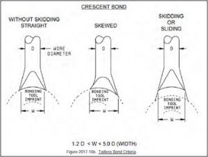
Fig. 2: Crescent bond squash out criteria
The ultrasonic energy delivered to the tip of a tool has a direction to it. It’s a vector in a sense. Piezoelectric crystals convert the electrical energy into vibrational energy and the best crescent bonds are made when the energy flows down the length of the wire. Operators on manual machines can make bonds by bonding in the 3 and 9 o’clock position. However, the ultrasonics at the tip roll across the width of the wire and form a sub optimized “skewed” looking crescent as shown in Fig. 3. Most automatic wirebond equipment compensate for this effect.
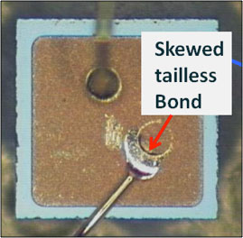
Fig. 3: Skewed bond footprint
Wedge Bonds
Fine wire wedge bond inspection criteria was recently tightened up in TM 2017. For gold or aluminum wire the max squash out on the deformed wire is 2X as shown. A squash factor W, less than 1.2 times or greater than 2.0 times the wire diameter is cause for reject (Fig 4). For most high yield wedge bond processes a squash factor of 1.3 to 1.6 X is generally in the optimum range.
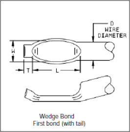
Fig. 4: Wedge bond squash criteria
1.2D < W < 2D
Approaching the upper spec limit of 2X, especially for aluminum wire, is cause for concern. Heel cracks at the junction of a bond pose a reliability risk. A one mil aluminum wirebond squashed out 2X, or 2 mils, potentially has a heel crack. This heel crack (Fig 5) may or may not be observable at the recommended 30 to 60X magnification range for inspection. There are many causes for heel cracks e.g. too much power/force, not hitting flat or too sharp a bend radius on the wedge tool. Excessive looping can also be a cause for heel cracks at the junction of first bond. Aluminum wire work hardens. It’s like a coat hanger, give it a couple of bends and it breaks.
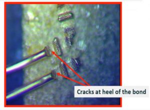
Fig. 5: Heel cracks in a 1 mil AU wedge bond 200X
Probe Marks
Before a wirebond of any kind is attached to an IC or MMICs (monolithic microwave integrated circuit), the operator/inspector must inspect the device for excessive probe marks, bond pad contamination, corrosion or staining that may be evident at the bond pad. The inspection criterion that pertains to bond pads prior to bonding is contained in the high mag section of TM 2010 beginning in para. 3.1.1. Recommended magnification for bond pad inspection is 75X to 150 X. Wafer probe marks greater than 25% of the bond pad area and expose underlying passivation are cause for rejection. Heavy probe marks (Fig 6) may damage the IC and missing metal underneath a bond weakens the interconnect. This criterion is a function of bond pad area so in some cases the pad may fail the inspection criteria, but there is still plenty of room to bond on undisturbed metal. In other cases, such as the gate pad on a microwave FET or schottky diode, every bit of bond pad is needed to form a reliable bond.
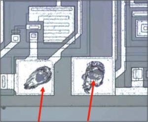
Fig.6 : Excessive probe marks from wafer test
Summary
MIL-STD-883 wirebond inspection criteria were developed over many years and are intended to cover a broad range of technologies. The visual inspection criteria contained in both TM 2017 and TM 2010 contains a lot of wisdom and serves to this day as the defacto standard. For QML (Qualified Manufacturers Listing) suppliers it is a contractual requirement, but for most it’s a guideline and a great starting point. In some cases the inspection criteria is lenient and in others spots overly restrictive. It’s important to have a clear understanding of the baseline requirements. In many cases the inspection criteria needs to be further tailored and enhanced with clear colored pictures to meet the customer requirements.
CLICK HERE TO DOWNLOAD FULL TECHNICAL PAPER PRESENTED AT IMAPS 2017 IN RALEIGH NC

Workmanship Standards eBook: Hybrids, Microcircuits and RF/MMIC Modules
Access over 300 color defect pics linked directly to the source requirement in MIL-STD-883.
Subscribe to the online Workmanship eBook and stay current with the latest industry best practice and up to date Mil Spec visual inspection requirements.