
Die Attach Voiding Requirements in Eutectically Bonded GaAs and GaN MMIC Power Amplifiers
September 19, 2016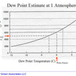
Hermetic vs “Near Hermetic” Packaging A Technical Review
September 21, 2016
New Release Of Mil-Std-883 Visual Inspection Criteria
Course: Pre Cap Visual Inspection Webinar: Visual Inspection Of Microelectronic Assemblies In-Plant TrainingTM 2017 and TM 2032
The next update to Mil-Std-883 (Change Notice 5) is expected to be released in June of 2015 and will include significant changes to two important Test Methods that contain the visual inspection criteria for Hybrids and RF MMIC modules (TM 2017 Internal Visual Hybrids) as well as an overhaul of the inspection criteria for passive components TM 2032 (Internal Visual Inspection of Passive Elements). Mil-Std-883 is a collection of test methods for microcircuits.
These test methods are relied upon in the military/aerospace industry, but are also widely used and referenced in the medical device community, telecommunications, oil and gas exploration industry and other hig rel applications. Most are familiar with MIL-STD-883 tests such as Temp Cycle (TM 1010) or Burn-In (TM 1015). However, four of these 883 test methods actually contain the visual inspection criteria that is used and referenced in accordance with Mil-Prf-38534 (Hybrids) or Mil-Prf-38535 (Monolithic ICs). They are:
Mil-Std-883 Description
TM 2009.11 External visual Inspection
TM 2010.14 Internal visual (monolithic)
TM 2017.10 Internal visual (hybrid)…….also known as Pre Cap Visual Inspection
TM 2032.2 Visual inspection of passive elements
[ws_table id=”1″]
As part of JEDEC (Joint Electron Device Engineering Council) these test methods are reviewed and scrutinized in committees made up of volunteers that meet on a regular basis three times a year. Proposed changes to these test methods are then submitted to DLA Land and Maritime located in Columbus OH for review, coordination and incorporation into the military standards.
The pending changes to TM 2017 and TM 2032 have been in committee review cycle for more than 5 years. Hybrid Pre Cap inspection (TM 2017) is required just prior to hermetic seal and this method further references the high mag IC die inspect criteria in TM 2010. In addition, TM 2017 also references TM 2032 for passive components like Ag/Pd end terminated MLCC (multi-layer chip capacitors) and Mil-Std-750 for diodes, transistors and power MOSFETS.
The new version TM 2017, includes the addition of photos and updated diagrams and wording changes designed to simply the criteria. Two specific changes worth noting are: 1) a tightening of the wirebond “squash” criteria for fine wires and 2) a tightening of the epoxy fillet criteria for non-planar elements such as a MLCC.
The new wedge bond wire squash criteria is now categorized according to wire size i.e fine wire (4 mils or less in diameter) and heavy wire (diameter greater than 4 mils). As shown in FIG 1 the wire deformation or “squash” factor historically was 1.0X to 3 X the wire diameter. The new requirement is a little more restrictive, but makes a lot of sense from a technical perspective. First of all it’s hard to squash a 1 mil aluminum wire 3X the wire diameter, even a 2X squash factor runs the risk of cracking the heel. Studies have shown optimum wire deformation to be in the neighborhood of approximately 1.3X to 1.6X the wire diameter.
An operator’s first instinct when the wires are not sticking is to turn up the power on the bonder. No sticks are often times due to surface contamination. A heel crack in a 1 mil Al wire is difficult to inspect and detect at the recommended 10-60 X magnification range, but this tighter criteria will hopefully help to safe guard this type of latent manufacturing defect. An increase on the low end of the “squash” range from 1.0 to 1.2 X also makes sense since it’s important to see some wire deformation to assure the ultrasonics have travelled through the wire and coupled into the bond pad.

FIG 1: Revised TM 2017 Wedge Bond Criteria 1.2D < W < 2.0D
The other significant change to TM 2017 involves the epoxy fillet inspection criteria for end terminated elements, which are often used inside hermetically sealed hybrids. As shown in Fig 2 the new TM 2017.11 version requires at least 75% epoxy coverage visible along each end and 50% epoxy visible around each of the 4 side views.
In the world of hybrid assembly it’s not unusual to have a MLCC break loose during centrifuge testing. Each hybrid is subjected to at least 3Kgs of force in the Z axis during screen testing. Due to the relatively high mass and small bond area footprint of the end terminations the force applied to the epoxy joint can be significant. This tightened visual criteria should help to keep the caps glued down.
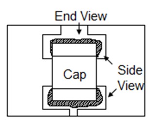
FIG 2: New epoxy fillet criteria requires 75% coverage on end and 50% fillet around each side.
However, there is a downside risk in that a greater volume of wet epoxy may be required to meet the new visual criteria and possibly risk electrical shorting underneath the capacitor as shown in FIG 3, especially for the smaller component sizes. This type of a latent defect may go undetected for small component sizes so Pre Cap inspectors need to pay special attention to this spec change.

FIG 31: Silver epoxy short underneath MLCC due to too much dispensed epoxy.
TM 2032 (Visual Inspection of Passive Elements) has also been updated with quite a few new modifications and updates to the inspection criteria. The previous version TM 2032.2 dates back ten years. The purpose of this test method is to inspect passive elements used for microelectronic applications, including RF microwave modules.
This test can be performed at the un-mounted element level, or prior to sealing or encapsulation to detect and eliminate elements with visual defects that could lead to failure in normal application. This criteria is focused on planar thick and thin film resistors and non-planar capacitors and other passive elements that are often used as building blocks for hybrids and multi-chip modules.
The visual inspection criteria contained in Mil-Std-883 contains a lot of wisdom and adherence to this spec is a value add especially for low volume complex microcircuits intended for critical high rel applications. On the other hand compliance with these specs is no guarantee of 100% reliability. Not all technologies are adequately addressed in 883 and much of the criteria represents industry best practice circa 1990 timeframe.
___________________________________________________
Ref 1: Workmanship Standards…Hybrids, Microcircuits and RF MMIC Modules
Microelectronic materials and process have improved tremendously over the past 20 years, but still a good visual inspection prior to hermetic lid seal is worthwhile. Training is also very important. At the end of the day it comes down to making good judgements about the hardware. Inspectors need to understand the criteria and the details of the process and be able to put it into practice on the manufacturing floor.
This understanding comes from years of real world experience and hours of hands on training in practical lab settings. On line training webinars can also be a cost effective way to supplement learning acquired on the factory floor.

